Modules
3 minute read
LisRT modules can be added to the respective application on a project-specific basis. For instance, a module can be a hardware device, a database connection or the loaded type data.
Module tree: What’s on it?
In the main window the module tree can be opened under . Depending on the access rights of the user, individual tools are disabled.
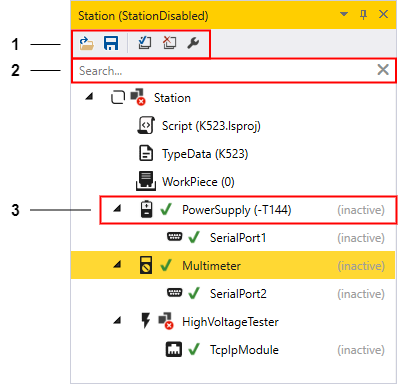
Figure 1. Module tree
-
Toolbar of the module tree
-
 Load configuration
 -
 Save configuration
 -
 Initialise all modules
 -
 Deinitialise all modules
 -
 Open the service window of the selected module (here of the multimeter)
-
-
Module search: Search for module names or device labels
-
Successfully initialised module
-
 for a successfully initialised module
 -
PowerSupply: Name by which Python script accesses the module
-
-T144: Device label, is configured in the configuration file
-
(inactive) indicates whether the module is deactivated in the loaded configuration file
-
The tool symbols for the module states are listed below:
-
 The module is not initialised
 -
 The module is being initialised
 -
The module has been successfully initialised
-
 The initialisation of the module has failed
Module configuration file
The LisRT application consists of many individual modules.
Plant-specific values, such as the COM port of a serial interface or existing hardware components for the individual modules, are saved in a configuration file.
In the main menu, under , you can specify which configuration file should be loaded by default when the LisRT application is started.
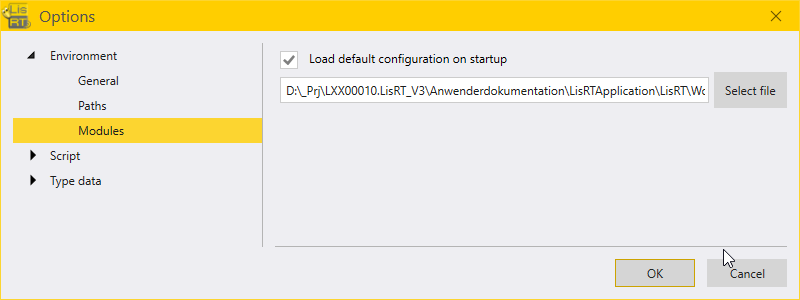
Figure 2. Path of the default configuration file
You can find the configuration files in the LisRT folder structure under LisRT\Workspace\Configuration\. Configuration files have the extension .config.
Loading an existing module configuration file
To load a configuration file manually, click on the load icon ![]() in the module tree () in the toolbar.
The old configuration, if any, is terminated recursively and the new module configuration is loaded into the modules and will be initialised.
in the module tree () in the toolbar.
The old configuration, if any, is terminated recursively and the new module configuration is loaded into the modules and will be initialised.
|
The configuration file can be loaded with the command line parameter |
Creating a new module configuration file
If there is no configuration file or if the module tree has been changed, i.e. if modules have been added or removed, proceed as follows:
-
Save
the configuration. A new file with the default settings of the modules will be created. -
Adjust the configuration file with a text editor.
-
Load
the adjusted configuration file.
Example from the configuration file
A comparison between the module tree and the module configuration file shows the same hierarchical structure in the format of the XML text file. The image below shows the corresponding section from the XML configuration file for the power supply PowerSupply and its submodule the serial interface SerialPort1 from Figure 3.
<Module Name="PowerSupply">
  <Properties>
    <!--Unit = 'V'-->
    <Property Name="MaximumVoltage">40</Property>
    <!--Unit = 'A'-->
    <Property Name="MaximumCurrent">2.5</Property>
    <Property Name="DeviceLabel">-T144</Property> (1)
    <Property Name="Enabled">False</Property> (2)
  </Properties>
  <Modules>
    <Module Name="SerialPort1">
      <Properties>
        <!--e.g. 'COM1'-->
        <Property Name="PortName">COM1</Property>
        <!--Unit = 'baud'-->
        <Property Name="BaudRate">9600</Property>
        <Property Name="DataBits">8</Property>
        <!-- Possible values: None, Odd, Even, Mark, Space-->
        <Property Name="Parity">None</Property>
        <!-- Possible values: None, One, Two, OnePointFive-->
        <Property Name="StopBits">One</Property>
        <!-- Possible values: None, XONXOFF, RTSCTS, DTRDSR-->
        <Property Name="Handshake">None</Property>
        <!---1 = Infinite Timeout-->
        <!--Unit = 'ms'-->
        <Property Name="Timeout">1000</Property>
        <Property Name="Enabled">False</Property> (2)
      </Properties>
    </Module>
  </Modules>
</Module>| 1 | Device label |
| 2 | If the respective module is not present or should not be used, the property Enabled must be set to false. |
Service window
Many of the modules have a service window which enables you to easily commission and diagnose the modules. It can be opened by double-clicking on the respective module in the module tree. For operating the service window:
-
The station has to be in manual mode

-
The operator must have the appropriate permissions.
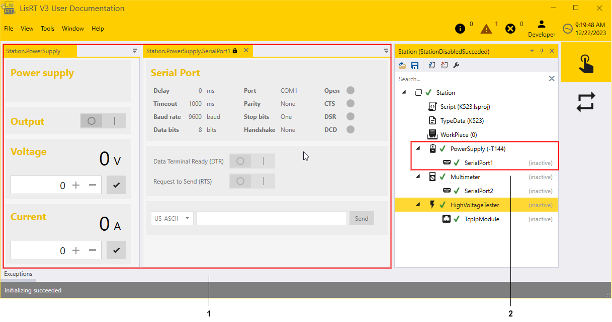
Figure 3. Service window of the power supply module with its submodule SerialPort1
-
The service windows of the power supply unit (PowerSupply) and the serial interface (SerialPort1) are shown as tabs
-
Module tree view of the power supply unit and the serial interface
Feedback
Was this page helpful?
Glad to hear it! If you have any suggestions for improvement write to us.
Sorry to hear that. Please tell us what we can improve.
Last modified 16.12.2024