Adjustment of Analog Inputs
Provides instructions for adjusting analog inputs in LisRT to ensure accurate measurements by compensating for tolerances in the measurement chain.
5 minute read
Analog inputs are used to capture measurements from connected sensors, such as voltage, temperature, pressure, etc. Since sensors provide different signals, such as 0-10V or 4-20mA, various converters, filters, and amplifiers are required throughout the measurement chain to convert the analog signals into digital measurements that can be processed by the LisRT application.
Signal Processing
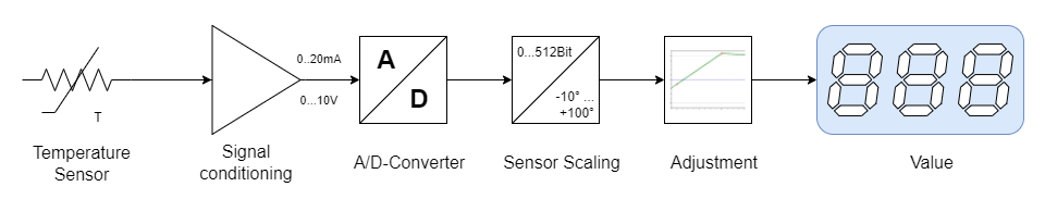
Figure 1. Components of the measurement chain
The components of the measurement chain are:
-
Sensor: Converts the physical quantity into an electrical signal.
-
Signal Conditioning: Filters and amplifies the sensor signal, providing a standardized 0-10V or 4-20mA signal corresponding to the sensor’s measurement range.
-
A/D Converter: Converts the analog signal into a digital signal. The higher the resolution of the A/D converter, the more accurately the analog signal can be converted into a digital signal.
Example 1. Resolution of an A/D ConverterA 12-bit A/D converter has 4096 (212) possible values. If the sensor’s measurement range is 0 - 100°C, corresponding to an electrical signal of 0-10V, then a bit value of 0 corresponds to 0°C, and a bit value of 4095 corresponds to 100°C. The resolution of the measurement in this case is 100°C / 4096 = 0.0244°C per bit.
-
Sensor Scaling: Converts the digital measurement value into the physical quantity, e.g., °C, bar, V, A, Ohm, etc. Scaling assigns the bit value to the sensor’s measurement range.
-
Adjustment is performed by comparing a measured value with the measurement of a calibrated measuring device. The correction values in the LisRT application are adjusted to minimize deviations.
Overview of the Service Window for Analog Inputs
The service window for analog inputs is divided into the following sections:
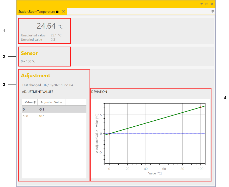
Figure 2. Service window for analog inputs
-
Value displays: Displays the adjusted value, the scaled value, and the raw value
-
Sensor measurement range
-
Adjustment with correction values
-
Graphical representation of the deviation between the adjusted and scaled value
Value Displays
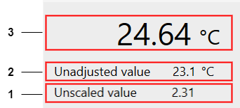
Figure 3. Value displays in the service window for analog inputs
The following values are displayed:
-
Unscaled value: This corresponds to the raw value provided directly by the A/D converter. In our example, the digital bit value converted to 0-10V.
-
Unadjusted but scaled value: This is the 0-10V converted into the physical quantity, e.g., °C.
-
Adjusted and scaled value: This is the value after adjustment, taking into account the deviations of the measurement chain.
Adjustment of Analog Inputs
All components of the measurement chain have tolerances that affect the accuracy of the measurements. To ensure high measurement accuracy, adjustment of the analog values is required.
Adjustment is performed using so-called correction values, which can be stored in the LisRT application. To determine the correction values, the sensor values are compared with a calibrated measuring device that has higher accuracy than the measurements to be adjusted.
|
For approximately linear sensor behavior, it is sufficient to capture two adjustment points. |
Adjustment
A measurement chain must be adjusted at least at two points. This compensates for offset and gain errors. Typically, the adjustment points are chosen at the lower and upper ends of the sensor’s utilized measurement range.
Example 2. Adjustment of a temperature sensor
The sensor connected to LisRT is placed together with the sensor of the calibrated reference measuring device in a water bath. The water bath is set to the first calibration temperature (e.g., 0°C), and the measurements of both sensors are read after a settling time and entered into the table. Then the water bath is set to the second calibration temperature (e.g., 100°C), and the measurements are read again.
The adjustment via the service window is straightforward:
(The input fields are activated by double-clicking and can then be edited.)
-
In the Value column, enter the unadjusted value of the sensor (e.g., 0°C or 100°C, see value displays)
-
In the Adjusted Value column, enter the measurement value of the calibrated measuring device (e.g., -0.1°C or 107°C)
-
The exclamation mark in the upper right corner reminds you that the adjustment has not yet been saved.
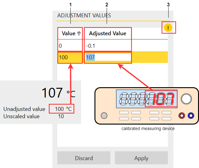
Figure 4. Value input in the service window for analog inputs
|
Adjustment is only possible with the appropriate permission. |
Non-linear Sensor Behavior
For non-linear sensor behavior, more than two points are required for correction to achieve an accurate adjustment. Additional intermediate values are recorded and entered in the service window:
-
Double-clicking on a row below the existing adjustment points inserts a new row.
-
The new row is automatically sorted into the correct position after entering the values.
-
A red warning may appear. This happens because a new row with the value 0 is suggested, but this value already exists.
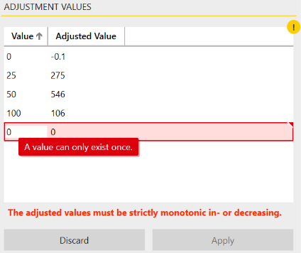
Figure 5. Additional adjustment points in the service window for analog inputs
|
A row can be deleted using the Del key. |
The resulting characteristic curve would look as follows:
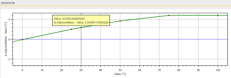
Figure 6. Characteristic curve with multiple adjustment points
The measurement value is determined by linear interpolation between the nearest adjustment points.
|
If the mouse pointer is dragged to a point on the characteristic curve while holding down the left mouse button, the deviation for the respective measurement value is displayed. |
Please Note
|
The adjustment of the analog inputs should be regularly checked and adjusted if necessary to ensure high measurement accuracy. Some sensors may change or age over time, leading to deviations in the measurements. |
|
When replacing the sensor or any other component of the measurement chain, the adjustment must be performed again, as the measurements may change. |
Feedback
Was this page helpful?
Glad to hear it! If you have any suggestions for improvement write to us.
Sorry to hear that. Please tell us what we can improve.